Module 13: Treatment Volumes and Treatment Planning in Proton Therapy
This content is no longer being maintained or updated. While it is available for review, please keep in mind the dates of creation, since some information may no longer be current.
For up-to-date proton therapy education designed for healthcare providers, please visit the Penn Radiation Medicine Institute. Current training and educational materials are available through our partnered and purchased programs.
Treatment Volume, Lateral and Distal Margins
Much like photon based therapy, with proton based therapy a gross tumor volume (GTV) that encompasses all clinically demonstrable disease is defined during proton treatment planning. An expansion from this, the clinical tumor volume (CTV) is then created to encompass microscopic disease. A planning target volume (PTV) must then be added to the CTV to account for two factors, uncertainties in patient setup and any variation in tumor size, shape and location within the patient. The volume that accounts for the internal uncertainties (i.e. changes in tumor location, size and shape) is formally called the internal target volume (ITV).
In proton therapy great care must be taken in designing a PTV. Not only do the lateral margins need to be carefully considered, but also the deep margin (distal edge of the beam) due to the uncertainties related to the range of a proton beam. Therefore a beam of sufficient energy to provide a margin on the CTV that can account for both motion and range uncertainty must be selected. This is not the case for the lateral edge of the beam, which still must take into account the motion issues but do not have the uncertainty associated with the distal edge of the beam, resulting in a non-uniform PTV expansion in most cases. A non-uniform expansion may work in defining dose delivered by a single field, but using separate lateral and distal edge PTV's with multiple beams makes calculating the dose distribution much more difficult. Therefore, the uncertainty in the beams distal edge is usually built into algorithms which allow the user to design a PTV adjusting only for the lateral uncertainties (such as penumbra) because the range uncertainties have already been taken into account. Another important consideration regarding the distal margin is the higher RBE in the distal portion of the spread out Bragg peak. The increase RBE may lead to greater tissue effects at the distal edge of the beam, which should be accounted for during treatment planning, specifically with attention to the distal borders location relative to critical structures.
Much like in photon planning, organs at risk (OAR) should be defined. Additionally, a margin can be added to the OAR to form a planning organ at risk volume (PRV), which accounts for internal motion as well as setup error, much like a PTV. The area which is not encompassed by the CTV or by an OAR is termed the remaining volume at risk (RVR). This volume helps determine the dose to all remaining tissues and may be useful in estimating the late effects related to radiation including the risk of secondary malignancy.
As discussed previously, heterogeneities of the tissues through which the protons travel greatly affect the range of the protons. Hence when choosing beam angles it is important to try and minimize the amount of heterogeneous tissues through which the protons must travel. It is also desirable to avoid complex structures as a complex shape may make compensator design more complex (this can often be done with patching, which will be discussed later). Specific examples include the sinuses which have numerous air cavities and a complex shape. Furthermore, they have a variable amount of fluid in them on a day to day basis, which also complicates treatment planning.
Treatment Planning Software
There are several algorithms that treatment planning software packages can use to estimate dose. The simplest and fastest is the uniform-intensity beam algorithm. This algorithm is based on the dose distribution of uniform-intensity beams which are incident on a flat water-equivalent phantom. However, this algorithm is the least accurate, as it provides a poor estimation of the effects of complex heterogeneities in the beam path, and can not be used to estimate dose from a pencil beam.
A more accurate algorithm models dose by using multiple pencil beams to model the entire beam. This gives greater control as a pencil beam can be used to directly reflect the fluence at that point within the beam. The model then accounts for multiple scatter events and can predict the dose at any given point by summing the contributions of each pencil beam. This allows inhomogenous beams (such as in IMPT) to be modeled and can more accurately predict the effects of heterogeneities of the tissues through which the proton travels.
However, the most accurate way to model dose is via Monte Carlo algorithms, which are the gold standard for modeling dose. These models take pencil beam algorithms one step further and actually model the individual protons and their interactions with matter as they pass through the patient. The likelihood of a proton interaction is based on a random number which is generated from the best approximation of the probability of the distribution of interactions of the protons. Monte Carlo interactions estimate not only the interactions with the nuclear electrons but also nuclear interactions (which make up about 20% of proton loss over the range of a beam). Secondary particles can also be accounted for using Monte Carlo models. However, Monte Carlo models are computationally very intensive.
Evaluating Proton Therapy Plans
Evaluating proton plans share many similarities with evaluating photon plans, particularly IMRT plans. In similar fashion to photon based treatment plans, a dose volume histogram (DVH) can be used to evaluate the dose distribution to the treatment volumes as well as OAR. DVH's allows the user to determine several useful values such as the mean dose to a structure, the median dose to a structure, the maximum dose a structure receives, the minimum dose a structure receives, as well as several other parameters such as the V20 (volume of an organ that receives 20 Gy). Shown below, in Figure 1, are examples of DVH's from an IMRT plan and a two field proton plan for the treatment of a pancreatic tumor. Note the similarities in interpreting the dose to structures between the two DVH's. However, also note the difference in dose distribution to critical structures between the two plans.
Figure 1. Anexample of an IMRT DVH and a two field proton
DVH for the treatment of a pancreatic tumor.
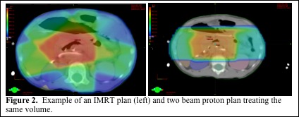
Proton dose distributions can be overlaid onto the planning CT to show the dose distribution to specific organs and areas of the tumor. The benefit of evaluating plans slice by slice allows one to see exactly where cold spots and hot spots are. In addition to this, it enables the user the ability to determine the proximity of the beam to critical structures such as the spinal cord, which can help determine if there is an adequate margin between the proton beam and critical structures. Given the previously mentioned uncertainty associated with the range of proton beams, it is critically important to evaluate the dose distribution at the distal edge of the beam to ensure adequate coverage of the tumor with margin as well as making sure the high dose distal edge of the beam is not at risk to enter critical normal structure due to set up error or internal motion. Shown below in Figure 2 are treatment plans for the same target volume (pancreatic tumor) using an IMRT plan and a two beam proton plan. Note that the proton plan uses the lateral aspects of the beam, where there is less uncertainty, to abut the spinal cord.
Volume Naming
In field naming, the International Commission on Radiation Units and Measurements (ICRU) has recommended that multiple nested volumes be labeled in a distinct fashion from spatially separated volumes. The ICRU recommends that nested volumes be listed by defined name (i.e. GTV or CTV) followed by further numeric designation (ex GTV1, GTV2). An alternative method recommended by the ICRU is to use the volume definition followed by the dose the volume is to go to (i.e. GTV-46 Gy (RBE), GTV-70 Gy (RBE). For spatially distinct volumes, the volume should again be listed by the defined name however, a second letter (i.e. GTV-A, GTV-B) should be used. Examples of how to use the ICRU nomenclature system are listed below in Figure 3. (Journal of the ICRU 2007 7(2):83-94).
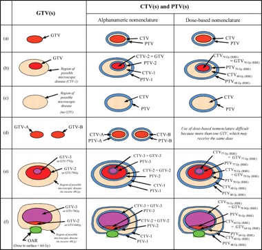
Figure 3. Schematic of how the ICRU recommended
nomenclature should be used in various treatment planning situations.
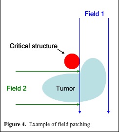
Match and Patch Fields
At present protons are most commonly delivered via a passive scatter technique. To improve conformality and reduce dose to critical structures, a patching technique can be used. With a complex shaped target volume, patching uses multiple beams, which only partially cover the tumor, to avoid a critical structure (figure 4.). Generally, the distal edge of one beam is matched to the 50% isodose level of the lateral penumbra of the field which it abuts. However, this creates a match point which has a non-uniform dose distribution. There are a number of factors which cause this inhomogeneity. First, the dose gradient at the distal edge of the beam combined with that of the lateral penumbra of the abutting beam can create cold and hot spots. Secondly, if the proton beams must travel through complex heterogeneous regions, this may cause uneven fall off at the distal edge of the proton beam, which also makes it hard to get a uniform dose distribution at the match. Finally, many of the algorithms used at present to create the shape of the compensator do not take scatter into account, which, especially when the proton beam is traveling through heterogeneous material, can lead to a substantial difference in intended and actual doses at the junction.
In order to help reduce these inhomogeneities at the match point, multiple patches can be used. With multiple patches, different patch junctions are created such that the match point can be shifted to a different place on alternating days. However, now additional fields are required which complicates set up and treatment planning and verification. Feathering can also be used with patching with the incident beam being broken down into several subfields, each matching at a different isodose level. This can be challenging as it requires precisely tuned accelerators and it can be difficult to determine the ideal isodoses to match to in order to limit inhomogeneity. However, there are a number of algorithms in the works to make matching patched fields easier.
Scattered Beams, Spot Scanning Beams and Intensity Modulated Proton Therapy (IMPT)
The differences between scatter beams and spot scanning beams have been discussed in module 3. Here we will focus on the use of intensity modulated proton therapy or IMPT. As a review, pencil beam scanning delivers dose to the tumor by scanning ÒlayersÓ of different proton energies to create a highly conformal dose distribution about the tumor. Unlike passive scatter beams, this means that the 100% dose is limited to the tumor unlike when a compensator is used. Another major advantage of spot scanning beams is that they do not require patient specific hardware, which reduces scatter to the patient (hence reducing total body neutron dose) as well as decreases the amount of time taken to switch compensators and apertures, which can slow treatment times.
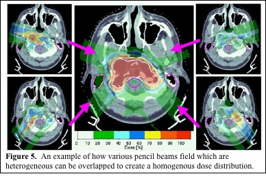
Scanning beams can also be used to deliver IMPT. The scanning beam allows dose to be delivered to a very specific site in a three dimensional area. By using several beam angles, a computer algorithm can determine the best way to deliver these discrete doses to conform to the tumor and avoid OAR. The algorithm can limit the dose delivered through heterogeneous tissues as well as through OAR to improve homogeneity and decrease dose to OAR (Figure 5. MGH). Hence, though each beam angle delivers a heterogeneous dose, the overlapping fields give a highly conformal, homogenous dose to the tumor, while maximally avoiding OAR. Scanning beams also have the potential to allow dose painting, with different doses delivered to different components of the treatment volume. While it may be possible to deliver IMPT using multiple scatter beams, it would require complex apertures and compensators and be greatly limited compared with IMPT using a scanning proton beam (Figure 5. MGH).
4D Conformality and Organ Motion
As discussed in module 3, the use of 4D CT scanning enables imaging of tumor and organ motion which can aid treatment planning. This is vital to proton treatment planning as the range of protons is highly dependent on the density and amount of tissue they traverse. This is of great concern in treating lung tumors due to the significant respiratory motion. Discussion regarding controlling organ motion for lung will be presented here, but is applicable to other disease sites affected by organ motion such as in pancreatic and prostate cancers.
Half of lung cancer tumors move between 0.5 to 1 cm with respiration and 10% move greater than 1 cm. Two techniques can be used to account for this respiratory motion. First, an internal target volume (ITV) can be used to cover the entire area the tumor moves through. Secondly, respiratory gating can be used. Data from Massachusetts General Hospital has demonstrated intra-fraction motion of lung tumors on 4D CT scanning. There are also data that have demonstrated that the proton beam's distal edge moves more distally as the tumor moves out of the beam. Based on this motion the tumor could be under-dosed if the margins used are not adequate. Additionally, a critical structure behind the tumor may get overdosed if the tumor Òside stepsÓ the beam path. By combining the path of motion of the tumor seen on the 4D CT into one volume, an ITV can be created. Studies have demonstrated that when standard margins are used, the tumor is under-dosed whereas when an ITV is used, there was greater sparing of normal tissues (due to better control of the distal margin of the proton beam) and better target coverage. Gating can also be used to spare normal lung tissue with data demonstrating a 6% improvement in V5, V10, and V20 dose with gating.
Interfraction variation can also be a problem in proton therapy of the lung. Studies have suggested that as a lung tumor shrinks, the CTV coverage remained adequate. However, the cord, heart and contralateral lung dose can increase during the course of treatment. As the tumor shrinks, the proton beam range can increase, increasing the dose delivered to normal structures. There are also studies that have demonstrated that the density of a lung tumor changes over the course of radiation therapy based on CT data. This study found that the contralateral lung was inversely proportional to the density of the CTV. This change in density was thought to be responsible for a decrease in CTV coverage from 99% to 92.3% with the use of protons over the course of treatment. This change in CTV dose was not seen in IMRT plans. In order to account for this, adaptive proton therapy may be used. It is vital to note any unexpected toxicity as this may indicate a change in the tumor or patient positioning.